As the other unipolar schemes, the unipolar non-return-to-zero inverted scheme uses two non-null voltage levels to represent the bits. There is, however, one key difference between this scheme and the level one: each binary value doesn't have a fixed voltage level. Instead, the representation of that bit will depend on the level used to represent the previous bit. Therefore, the logic to determine the voltage level for each bit is as follows:
- Bit 0: maintain the current voltage level.
- Bit 1: toggle the current voltage level.
Since the representation of each bit depends on the previous one, in order to correctly represent a section of the binary array it's necessary to know which was the previous voltage level. The plot generator in this learner already takes this into account, and allows you to choose which previous voltage level is be considered at the beginning of the plot.
Just as with the non-return-to-zero level scheme, this scheme still faces problems with synchronization over long sequences of identical bits. However, this issue is less problematic here than in the other scheme mentioned, for only a long sequence of 0s can cause a potential loss of synchronization. Furthermore, the fact that this scheme is based on change rather than on the absolute value of each bit makes it more robust to polarity inversion (which is useful in some hardware setups).
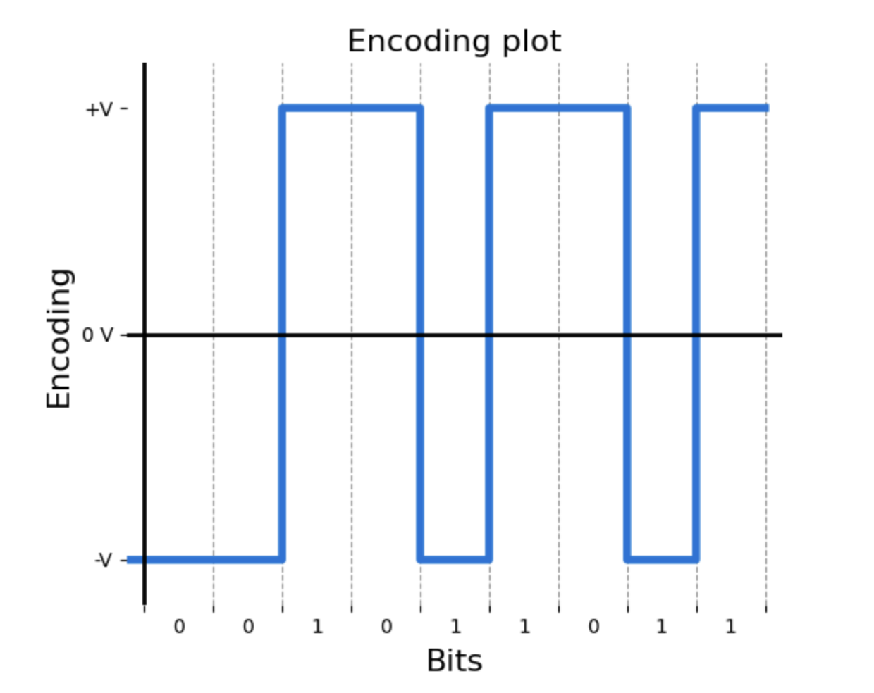
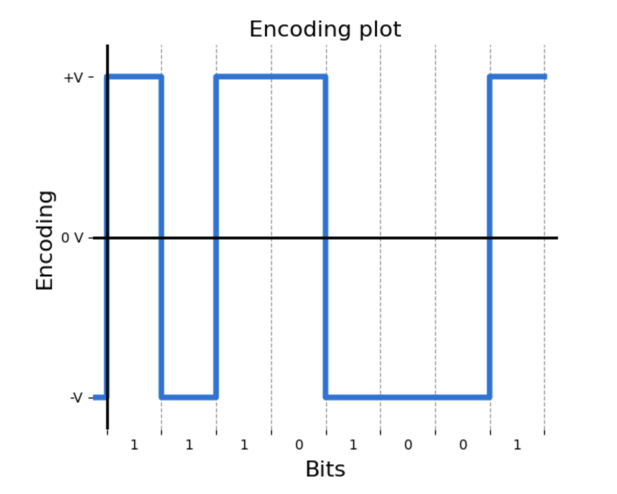
Below are a few examples of the Unipolar non-return-to-zero inverted scheme.